Introduction to OpenCascade and CAD modelling kernels
This article is mostly a recording of the corresponding CAD programming lesson we published on our youtube channel. In this series, we cover the basic aspects of the geometric modelling discipline and give an introduction to the OpenCascade library from a practical perspective.
 |
Welcome to CAD programming lessons. |
Today let's talk about the modelling kernels in general and the position of OpenCascade on this market.
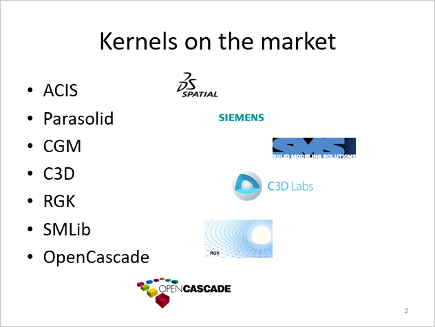 |
Some interesting CAD kernels. |
OpenCascade is not alone, and if we list all other CAD kernels, we will get just a handful of libraries, which deserve some discussion, all written in C/C++ language. ACIS and Parasolid are the most well-known and respectable commercial kernels among them, and many CAD modeling packages rely entirely on them. For example, SolidWorks is built on Parasolid, whereas ACIS undergrounds SpaceClaim. Then there's the Catia Geometric Modeller, also known as the Convergence Geometric Modeller for marketing reasons, which serves as Catia's backbone.
There are a couple of new libraries. And the first one is the commercial kernel C3D (www.c3dlabs.com), which is a pretty remarkable software package backing the locally popular CAD system Kompas. Unlike other players, C3D developers publish their documentation without any restrictions, and they seem to compete with OpenCascade a lot, struggling for a market share in the niche of affordable CAD engines.
Then we have RGK (www.rgkernel.com), which is a little bit of a phantom thing. It has never been released as a product for licensing, but it is a quite intriguing project. RGK had sparked interest in CAD, and it served as a catalyst for individuals to conduct academic studies on CAD and all of these traditional algorithms, such as Boolean operations. You could think that Boolean operations and other modelling functions are old news and largely solved problems. However, this is not necessarily the case. Because geometric modelling algorithms are evolutionary beasts, there is rarely a right or wrong way to implement things, and a single modelling problem can be approached in a variety of ways. Of course, there are some cutting-edge methods as well as some strong and weak approaches, and RGK served as yet another attempt to reexamine foundations and construct a full-featured CAD kernel from the ground up. We can't call this project a failure because there's still nothing to test, but we also can't call it a success for the same reason. Still, some interesting papers were published, and our area has taken on a fresh start thanks to new participants.
After that, there is SMLib (www.smlib.com). Despite its limited adoption, I wanted to include this library on this list. SMLib is remarkable in at least two ways. The first thing to note is that SMLib is based on cutting-edge scientific articles. Actually, SMLib is based on the algorithms from "The NURBS Book." "The NURBS Book" is the primary resource for those attempting to implement NURBS computations from scratch. Another interesting aspect of SMLib is the way it is licensed. Other commercial libraries typically only provide binaries rather than sources. The sources of SMLib could also have been obtained, at least when I first discovered the library. And this means that if the vendor company goes out of business, you are somewhat secured.
However, access to sources is more than just a legal concern. It is simply useful to be able to look into sources to find out how to call one or another function. In many ways, the source code serves as the best documentation. Personally, I'd like to have sources so that I can better understand the mechanics of what's going on under the hood. Sometimes you can save a lot of time by just noticing that you're calling an API procedure with the wrong inputs that, for example, fail its contract checks. And this idea of source access consequently brings us to OpenCascade.
OpenCascade is the only open-source kernel on the list, which is why we like it. However, you may say that OpenCascade does not stand out in terms of features, as it lacks any innovative capabilities. Yet, it actually works. It allows us to create and manipulate objects in 3D for a variety of technical and even non-engineering applications. So let's see what we get with OpenCascade. But, before we delve into it, I'd like to talk about the technology that underpins all of the listed kernels.
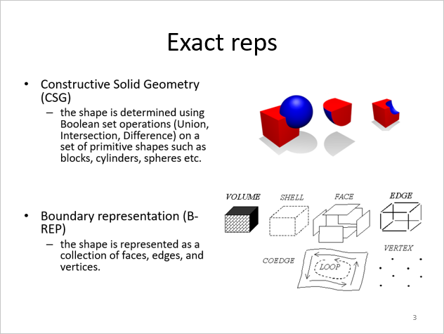 |
CAD model representation schemes (CSG and B-rep). |
When you first start modeling, you must consider how you will represent the product in such a way that a computer can handle it. How would you digitalize your shape so that you could ask your system various geometric questions and receive unambiguous answers? And the fundamental question to ask is whether an arbitrary point in an ambient space belongs to an object you are about to represent. Because if we can get our system to answer this basic query, we will potentially know where the object is geometrically embedded in the space. This question gets us to the "Point Membership Classification" problem, abbreviated PMC. PMC is not a little thing, and there are numerous ways to answer it. There is one commercial-grade technology that has been proven over decades of industrial use. It's called the boundary representation, or simply B-rep. Still, the boundary representation technique is not alone.
To begin, there is another, older technique known as Constructive Solid Geometry, or CSG. In CSG, you have a list of primitives that have been analytically defined. For example, a sphere is defined by its center and radius, whereas a box is defined by its corner position and dimensions. You get your final shape by arranging these primitives in a tree, which is essentially a program or declaration of how to construct your final geometry as a result of the Boolean operation series. There are advantages and disadvantages to this CSG approach. The main advantage is that it ensures that the final shape is sound and flawless, regardless of what the operands are. In the worst-case scenario, the CSG program will just return an empty result. However, if you combine your primitives in a way that assumes some result, you will end up with a completely valid state of geometry, because there is no way to break this whole thing. In CSG, you do not actually evaluate the boundaries, so you do not have them directly in memory. You would rather tackle this PMC issue with regard to the CSG tree declaration. As long as there is no computation, you are safe and sound.
We can say, "Okay, CSG is a kind of boutique technology, and it's kind of dead." However, this is not an entirely correct statement. Now CSG has evolved into another incarnation of traditional feature-based modeling solutions like SolidWorks. It still finds its niche. Indeed, what exactly constitutes a feature? Consider the stock volume of a material where you want to drill a hole by performing a Boolean operation on the stock shape and the feature shape. Whatever representations these operand shapes have, you'll end up with a tree of Boolean operations or other modelling operations that look fairly similar to CSG. The operand shapes and their relationships must be stored somewhere in your specification or, for example, feature tree. So, whenever you change a design parameter, your CSG is evaluated again to produce a new shape.
However, vanilla CSG is not the greatest technology out there. The most natural way of expressing a shape is to explicitly describe all of its boundary surfaces. And here is when boundary representation enters the scene. The purpose of boundary representation is to provide precise mathematical equations for the surfaces that establish the exterior of your CAD part in 3D. We can go into great depth regarding the underlying data structures of B-rep and how this entire shape representation is achieved by breaking it into topology and geometry, but these are only implementation details. The essential idea stays intact: we need to solve PMC. All you need to do in B-rep is define your model's surface using computational geometry. This is where the entire modelling business begins to sound really scientific. We just have a set of completely correct mathematical equations for all of the surfaces and curves that make up our model's boundaries. Using boundary representation, we can easily sample our models and obtain all of the points on the boundary without having to use any complicated numerical methods. However, the point membership classification problem persists, and you'll need to perform some complex computations to classify a point with respect to the boundary: is a point inside, outside, or on the model's boundary? To figure this out, you'll need to do point inversion (projection) because you only have surface parametric equations, which are insufficient to reason about enclosed volume. In this aspect, B-rep is less convenient than CSG.
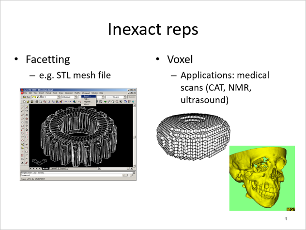 |
CAD model representation schemes (facets and voxels). |
Then there is another technique that is a subset of boundary representation: facet or mesh modelling. There is still an explicit set of boundary elements, but the elements themselves are much simpler. They are even called this way: "simplexes." Here, you limit your boundary representation to a few primitives, such as triangles and straight line segments. This allows you to greatly simplify the underlying data structures. You no longer require parametric equations for curves and surfaces; all you need is an unstructured grid, similar to a list of primitives made up of nodes that appear in a specific sequence. You're not really concerned with the differential or local properties of your surface elements. This is a very popular way to modelling, particularly in the computer graphics field, such as gaming or sculpting, because it results in incredibly efficient and robust modelling algorithms. The disadvantage of this modelling approach is rather evident: you model for shape but not for accuracy. Accuracy is sort of sacrificed for better efficiency, robustness, and simplicity.
However, if you are interested in feature-based modelling scenarios or typical CAD applications such as CNC machining, you will need to work with features. Because generating milling pathways requires knowledge of the particular surface types. Also, you might want to run a numerical simulation that requires you to construct a finite element model of your shape, which is difficult to generate from mesh representation unless you have a link to the actual CAD model. With a pure mesh model, precision is limited, and you do not have the luxury of having an ideal form representation, or a "master shape," from which all derived representations can be generated. That is why faceted representations are considered secondary in the field of computer-aided design. We can always produce facets with a certain level of detail from the precise boundary representation. However, the opposite problem is way more challenging because there is no complete and automatic solution out there.
Another method of representing shapes is voxelization. It's a decomposition scheme in which you try to describe the ambient space in which the object is embedded rather than the object itself. You can utilize a variety of methods here, ranging from straightforward and simple uniform decomposition, which produces a 3D raster image, to more complex decomposition schemes such as adaptive distance field. Such adaptive systems are more compact and can save a significant amount of memory and CPU resources.
There are various other techniques to shape representation that are more exotic and not included in my slide deck. To provide you with a reference, you can look up what is known as a functional representation, or F-rep, but we won't go into detail here because it's a specialized technology that hasn't gained much favor in industrial applications.
 |
ISO 10303 (42) comes up with a choice for us. |
Given the wide range of shape representation schemes available, how would we choose one? Fortunately, this decision was largely made for us because the ISO 10303 (42) standard defines boundary representation as the ultimate way of representing a digital object. So, if you wish to comply with a generally established standard, you should use a B-rep modeller.
That's hardly surprising, given that boundary representation is very similar to old-school drawings. You know, all these drawings that are made up of two-dimensional lines, circles, and splines. Drawings remain popular in mechanical engineering even today, when people talk a lot about MBD design, digital twins, and what not. The 3D boundary representation approach takes drawings to the next level by adding another dimension and eliminating ambiguities in the geometry described. If you have materialized entities as the boundary elements (faces, edges, and vertices), you may attach other properties, such as dimensions and tolerances, or even design review notes, directly to the graphical entities on your screen.
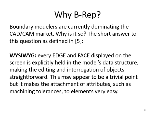 |
B-rep rocks. |
To summarize, boundary modellers dominate the CAD and CAM fields. The fundamental reason for this is that B-rep hits the ideal mix between computational efficiency and human-centric clarity. Boundary representation is the obvious successor to the drawings that humans have employed for centuries, if not thousands of years. In this aspect, B-rep is a trade-off that provides sufficient convenience for both computer and human perception. Again, you can tie your attributes, tolerances, and so on to something substantial rather than to a plethora of inaccurate voxels or mesh elements that you never know what features they actually describe.
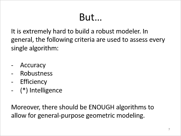 |
Okay, B-rep rocks, but... |
So, while boundary representation is beneficial in many ways, it just sounds to good to be true. The challenge is that it is extremely difficult to develop an efficient, robust, and accurate boundary modelling kernel. So we are not going to implement one; instead, we will start with the OpenCascade kernel, which includes all of the necessary functionality right out of the box. In the following lessons, we will go over OpenCascade in deeper detail.
Want to discuss this? Jump in to our forum.